Reliable PV Connectors – Background
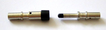
Fig. 1 – Pin and socket of a photovoltaic connector.
Photovoltaic modules have no moving parts and last upwards of 25 years with no maintenance aside from the occasional cleaning. Realising such a long lifetime for entire PV systems relies on the continued integrity of all system components. New applications for photovoltaics such as roof shingles place further performance demands on electrical connectors such as shown in Figure 1. The dc interconnection between PV elements represents a potential weak link in a PV system.
PV connectors within roofs and facades expand and contract on a daily basis, which can lead to small amplitude movement at interface surface of a mated connector – this is commonly known as fretting. In time, the fretting process wears the surfaces of the connector, leading to a build up of wear debris, which can result in eventual connector failure. Certain metallic platings for copper; the conductor of choice; are less prone to fretting and corrosion than others – ideally gold would always be used but cost dictates alternatives are required for PV systems.
Tin is often used as a plating metal being resistant to corrosion and of low cost. However, tin has two major drawbacks (i) tin rapidly forms an insulating oxide in air which must be penetrated by the surfaces of a connector when mated, (ii) tin is prone to fretting wear. Alternative platings such as silver and palladium are also used but these are more expensive.
Reliability Testing of Photovoltaic Connectors
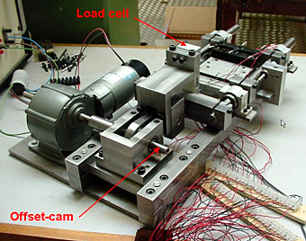
Fig. 2 – Accelerated fretting rig – 1 connector on test.
An accelerated lifetime fretting rig has been developed to test presently available and PV prototype connectors. The test rig, which is shown in Figure 2, has the following features:
- Up to 8 connectors on test simultaneously.
- Measurement of compression and tension loads.
- Precision 4 wire temperature compensated, dry-circuit resistance measurement.
- Controlled environment chambers for humidity and corrosive gas testing.
- Fretting amplitude measurement.
- Variable fretting amplitude 10 – 100 microns.
- DC current cycling of connectors (up to 20 A).
- Simulates 25 years of field use in 15 hours.
Fretting Behaviour of a PV Connector
Fig. 3 – Typical fretting behaviour of a PV connector.
The typical fretting behaviour of a rigidly held PV connector under accelerated fretting testing is shown in Figure 3. A gradual increase in contact resistance is seen until event ‘A’ after approximately 10,000 cycles. Thereafter a sudden ‘run-away’ increase in contact resistance to an an open circuit value can be observed. The fretting amplitude of the test rig increases at ‘A’ due to a sudden reduction in the normal force which retains the mated connector components.
In the operating environment of a PV roof or facade the differential thermal expansion of components creates the fretting effect on a daily cycle. If we assume that 1 fretting cycle occurs per day, 25 years would correspond to 9160 cycles. The connector in Figure 2 exceeds a 25 year lifetime even under very high amplitude fretting condition. Selective use of flexible housings can ensure that far lower fretting ampltiudes occur at the connector interface for rigidly held connectors, leading to reduced wear of plated surfaces and extended lifetime. PV connectors used as ‘flying leads’ to interconnect PV modules for example are subjected to far smaller fretting amplitudes.
Key results have been published in:
Bahaj A.S., James P.A.B. and McBride J.W. (2003), Predicting photovoltaic connector lifetime. Proceedings 3rd World Conference on Photovoltaic Conversion, WPEC3, 12-16 May 2003, Osaka, Japan, pp 2046-2049. View paper.